1. Wear and Abrasion
(Abrasive Wear, Fatigue Wear, Adhesive Wear)

Surfaces in pumps, valves, or actuators can experience direct contact under load, gradually shedding material.
Fuel: Sliding contact between a fuel pump plunger and barrel can release fine metal particles into the fuel stream.
Hydraulic: Servo valve spools wearing against their sleeves can generate fine metallic debris that affects valve response.
Lubrication: Journal bearings in a gearbox shedding bronze or babbitt particles when oil film is insufficient.
2. Corrosion and Chemical Attack
Water contamination or incompatible fluids can chemically attack metal surfaces, making them prone to flaking.
Fuel: Microbial growth in fuel tanks produces acids that pit metal surfaces, releasing rust flakes.
Hydraulic: Water ingress in hydraulic fluid causes rust in steel components, shedding iron oxide particles.
Lubrication: Acidic oil (due to additive breakdown) etches bearing surfaces, generating corrosive debris.
3. Fatigue and Fracture
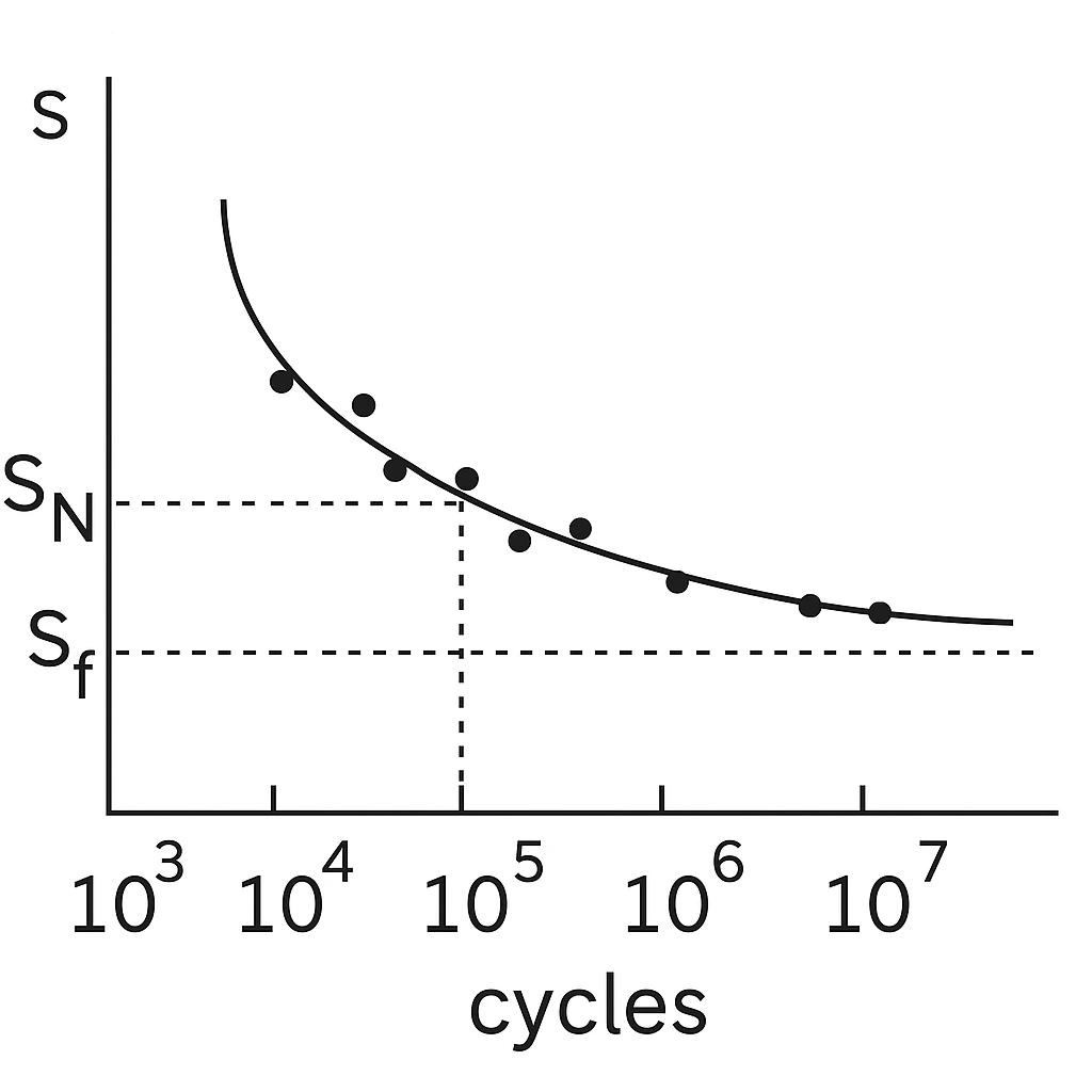
Repeated stress cycles cause micro-cracks that eventually release fragments.
Fuel: Repeated pressure pulses in fuel injector tips can cause cracking and small fragment release.
Hydraulic: Accumulator diaphragms or seals developing micro-tears that shed elastomer particles.
Lubrication: Rolling-element bearings spalling under fatigue, creating hard steel particles.
4. Impact or Foreign Object Damage (FOD)

Solid contaminants entering the system can chip away at internal components.
Fuel: Ingested dirt or loose tank debris damaging pump impellers or injector nozzles.
Hydraulic: Assembly debris (metal chips, gasket fragments) scouring actuator surfaces.
Lubrication: Gear teeth damaged by dropped fasteners during maintenance, creating chunks of metal.
5. Manufacturing or Maintenance Residue

Debris left over from assembly or repair can become a long-term contamination source.
Fuel: Thread sealant flakes from fittings dislodging into the fuel stream.
Hydraulic: Residual honing grit in cylinder tubes from manufacturing.
Lubrication: Lint from cleaning rags circulating in oil passages.