Home / Knowledge Hub / Alnico Chip Detector Demagnetization

Alnico Demagnetization in Two-Prong Chip Detectors

Part 1: The Alnico Problem

A two-prong chip detector that comes out clean at inspection is usually good news, but it can also hide a problem. Its magnet may be weaker than it was on the day it was installed, and nothing on the detector shows it, because a clean detector with a weakened magnet looks exactly like a clean detector with a healthy one. This article explains why the loss happens, why it follows from the choice of magnet, and how much it reduces capture.

Why Alnico in the First Place

Part 1 of 2. This article covers the magnets in two-prong chip detectors. Part 2 covers the disc-style detector, which solves the magnet problem and introduces a new one.

A two-prong chip detector places two small permanent magnets directly in the oil. The magnets form two prongs that stand proud of the mounting face, with an open chip gap between them. When enough debris collects to span the gap, it closes an electrical circuit and turns on a chip light. The representative detector modeled here uses two cast Alnico 5 rods, 0.125 in in diameter and 0.625 in long. The chip gap is 0.045 in, and the tips stand 0.220 in proud of the wall.

Neodymium (NdFeB) magnets are many times stronger than Alnico and far more resistant to demagnetization. Two-prong detectors use Alnico for durability. Sintered neodymium and ceramic (ferrite) magnets are hard and brittle. On an exposed probe, they can chip or crack if the detector is dropped, knocked against a fitting or snapped onto a steel tool. Cast Alnico is a tough metal alloy, and it does not shed fragments.

This matters because a magnet fragment is one of the most harmful forms of foreign object debris (FOD) in an oil system. Ordinary metal debris travels with the oil, where a filter or chip detector can catch it. A magnet fragment is drawn to steel. It attaches to bearings, gear teeth, pump parts and the inside of steel housings. It holds against the flow, and neither flushing nor filtration can remove it. It lodges in the components the detector was installed to protect. The detector it broke from is also left with less magnet, so it no longer performs as designed.

A chipped magnet is FOD that seeks out the most critical steel in the engine. The chip detector is degraded in the same moment.

For a magnet that must sit bare in the oil, Alnico is the sensible choice. The trade-off is stability.

Close-up of a two-prong chip detector: two Alnico prongs standing from the end of the body with the chip gap between them, and steel chips standing up on the tips and outer edges of the prongs
A two-prong chip detector with captured steel debris. The chips gather on the tips and outer edges of the two Alnico prongs, while the chip gap between them stays open.

The Knee of the B–H Curve

Every permanent magnet has a demagnetization curve. This is the part of its B–H loop that shows how much flux density (B) the magnet keeps when a reverse field (H) acts on it. A magnet in open air never operates at the top of this curve. Its own field passes back through it and pushes it partway down. The shape of the magnet sets how far, through the permeance coefficient (Pc). A long, thin magnet has a high Pc and operates near the top. A short, wide magnet has a low Pc and operates lower.

For neodymium, and for the samarium cobalt in a disc-style detector, the curve is a straight line over most of its length. It then drops sharply at the knee. While the magnet operates on the straight portion, a disturbance moves it down the line, and it returns fully when the disturbance is removed. No strength is lost. The N42SH ring in the NZMS operates far from its knee. It takes no permanent loss from stray fields below about 1,146 mT, more than a thousand times any field it will see in service.

Alnico behaves differently. Its curve bends across most of its length, and the bend falls in the range where a rod-shaped magnet operates. The Alnico 5 rods of a two-prong detector settle at Pc ≈ 14.5. At that point they carry only about 72% of the material's catalog remanence. This is below the maximum-energy point (Pc about 19), on the steep side of the bend and just past the knee.

Demagnetization curves of Alnico 5 and N42SH. The Alnico 5 curve bends sharply where the rod load line crosses it, and a stray field leaves the operating point permanently lower. The N42SH curve is a straight line with its knee about 1,430 kA/m away.
Left: the two-prong rods operate on the bend of the Alnico 5 curve. A stray reverse field pushes the operating point down the curve (2). When the field is removed, the magnet returns along a straighter recoil line and settles lower (3). The difference is a permanent loss. Right: the N42SH magnet in the NZMS operates on a straight line, far from its knee. Note the different horizontal scales.

In practice, an Alnico magnet does not return to its starting point after a reverse field is removed. It recovers along a straighter recoil line and settles lower. A strong field is not required. Because the rods already operate on the steep part of the curve, a small field is enough.

Stray Magnetic Fields

Our load-line and recoil-line analysis of the two-prong rods shows the scale of the effect. A temporary stray reverse field of only 1 mT leaves the rods about 1.0% weaker after it is removed. That is 10 gauss, about the field of a small refrigerator magnet a short distance away. A 5 mT field leaves them 5.1% weaker. There is no safe threshold. The loss begins with the first millitesla.

1.0%permanent loss in the Alnico 5 rods from a 1 mT stray field
5.1%permanent loss from a 5 mT stray field
0%loss in the NZMS N42SH magnet below about 1,146 mT
Line chart of permanent loss of magnetization against temporary reverse field from 0 to 50 mT, for Alnico 5 rods and an Alnico 5 ring shape, with N42SH and SmCo at zero
Permanent loss of magnetization after a temporary reverse field is removed. The two-prong rods lose strength from the first millitesla. A ring of the same Alnico 5 would lose far more, which is one reason Alnico is used only in long, thin shapes. N42SH and samarium cobalt take no loss at these fields.

Reverse fields are common in routine maintenance. Magnetic pickup tools, magnetic-base dial indicators and magnetic parts trays are often on the same bench as the detector. Spare detectors are often stored together. Two detectors placed side by side, or brought together with like poles facing, can expose each other to well over a few millitesla. Arnold Magnetic Technologies, a major Alnico producer, warns that bringing like poles of magnetized Alnico magnets together can cause a large loss [2].

None of these events is unusual. Each one costs a fraction of a percent to a few percent. The losses accumulate, they do not recover, and nothing records them.

Vibration, Shock and Handling

A chip detector spends its service life threaded into a gearbox or engine, under constant vibration. The Magnetic Materials Producers Association guidelines state that mechanical shock and vibration act on a magnet much like thermal agitation, moving it toward a lower energy state [4]. A magnet operating on the steep part of its curve, as the Alnico rods do, is the most exposed to this effect. Handling, including drops and knocks during removal and cleaning, is a recognized cause of partial demagnetization in Alnico [2].

The size of this loss is not known. KasperAero found no published reference that gives a measured loss per drop, or per hour of vibration, for Alnico 5. Long-term stability studies of Alnico address temperature rather than shock [6]. The result is a recognized loss mechanism that acts on a two-prong detector for its whole service life, with no published measure of its effect.

Heat and Cold

Heat is a strength of Alnico. Its field changes by only about −0.011% per °F (−0.02% per °C), and its metallurgy is stable up to about 1,000°F (538°C) [1]. Hot oil does not degrade a two-prong detector. In hot oil, the larger effect on capture comes from the oil itself, because thinner oil lets the magnet pull chips in faster.

Cold is a different case. Arnold's guidance on low-temperature use and the classic text by Parker and Studders both report that deep cold can cause irreversible loss in Alnico of up to 10% [3, 5]. Exposure depends on where the machine operates and how the detector is stored. It is one more way the magnet can lose strength without any indication.

The NZMS uses N42SH, a neodymium grade limited by heat rather than by stray fields. By the same knee calculation, irreversible loss would begin in the worst 1% of the NZMS magnet at about 300°F (150°C). This matches the manufacturer's maximum working temperature. Below that temperature, the risk of demagnetization is negligible. Higher-temperature grades in the same geometry raise the limit to 365°F (185°C) and beyond. The NZMS magnet is also sealed behind the sensing face. It cannot be dropped bare, chipped or brought against another magnet. The FOD concern that led chip detectors to Alnico does not apply.

How Much Does a Weaker Magnet Cost?

Per percent, a weaker magnet costs less capture than might be expected. Over a service life, the losses add up. The pull on a steel chip depends on how steeply the field changes. Away from the prong tips, that pull scales with the square of the field. A magnet that is 10% weaker pulls on a chip almost 20% less.

Capture falls more slowly than pull, because a chip that is pulled in later is often still caught. We ran the two-prong detector with weakened rods through our pipe capture model at the reference condition, with 250 µm steel chips in a 1.25 in bore of hot turbine oil:

Rod strengthCapture, rods in line with the flowCapture, rods across the flowChips missed compared with a new detector
100% (new)18.9%21.2%Baseline
95%18.5%20.9%about 2% fewer caught
90%18.0%20.0%about 5% fewer caught
80%16.9%19.1%about 10% fewer caught

A detector that has lost 10% of its strength misses about one more chip in twenty. On its own, that is a modest loss. The concern is the combination. The loss is permanent, it builds up from routine causes, and it gives no indication. It also applies to a detector that catches only about one chip in five when new. Independent laboratory testing measured roughly 8% to 28% capture for a production two-prong detector in hot oil. Every point lost comes from an already small number.

The only way to detect the loss is to measure the magnet against a known baseline, with a gaussmeter and a fixture, at every inspection. Few maintenance programs do this, and a visual inspection cannot reveal it.

The Thread Clocking Problem

A two-prong detector has one more variable, unrelated to the condition of its magnet. The detector threads into its port, so the angle of the prongs to the oil flow depends on where the threads stop and the lockwire aligns. One installation may have the rods one behind the other, in line with the flow. Another, on an identical gearbox, may have them side by side, across the flow. This angle is not chosen, and it is rarely recorded.
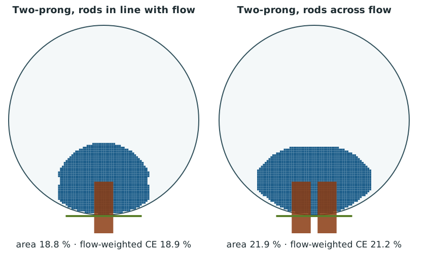
Two capture footprints looking downstream into a 1.25 inch pipe: a two-prong detector with its rods in line with the flow, where one rod hides behind the other, and the same detector with its rods across the flow, side by side
The same two-prong detector in two installed orientations, viewed looking downstream. Left: rods in line with the flow, one behind the other. Right: rods across the flow, side by side. Every 250 µm chip released inside the blue area is caught. KasperAero analysis, not test data.

We ran the rotation through the same pipe model, from 0° (in line) to 90° (across). The detector was placed on the side and on the bottom of the pipe, and also run with gravity off to isolate the magnet.
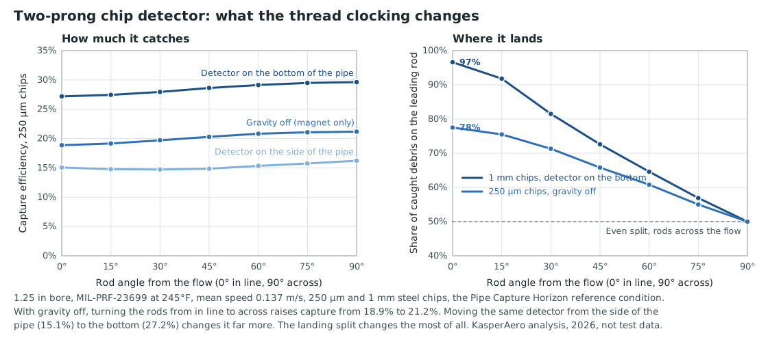
Two charts for a two-prong chip detector against rod angle from 0 to 90 degrees. Left: capture efficiency rises slightly from in line to across the flow. Right: the share of caught debris on the leading rod falls from 97 or 78 percent at 0 degrees to an even 50 percent at 90 degrees.
Left: capture rises slightly as the rods turn across the flow. The detector's position on the pipe has a larger effect. Right: the landing location changes substantially. With the rods in line, the leading rod collects most of the debris. KasperAero analysis, not test data.

The effect on capture is modest. With gravity off, turning the rods from in line to across raises capture from 18.9% to 21.2%. The port position has a larger effect. The same detector captures 15.1% on the side of the pipe, 27.2% on the bottom and about 7% on the top.

The effect on landing location is much larger. With the rods in line with the flow, the leading rod collects 78% of the captured 250 µm debris. With the detector on the bottom of the pipe, it collects 97% of the 1 mm chips. The trailing rod is shielded and collects almost nothing. With the rods across the flow, the split is even.

This matters because a two-prong detector indicates only when debris bridges the gap between the rods. Our field analysis shows that chips already favor the outer corners of the prongs over the gap. Independent laboratory testing found that the gap of a production two-prong detector bridged in only 10 of 36 runs. When nearly all of the debris collects on one rod, a bridge is even less likely. Two identical detectors in identical gearboxes, wearing at the same rate, can give different indications because of how far the threads turned.

Fine steel chips standing up in two clusters on the pole faces of a two-prong chip detector, with the gap between the poles clear
Steel chips gathered on the tips and outer edges of the protruding rods of a two-prong chip detector, with the gap between the rods still open
Debris on production two-prong chip detectors in independent laboratory capture testing. Left: chips standing up on the two pole faces. Right: chips gathered on the tips and outer edges of the rods while the gap between them stays open. The detectors were bought on the open market for this testing.

What the NZMS Does Differently

The NZMS was designed to avoid these problems. Its N42SH magnet is sealed behind the sensing face. This allows a strong, stable rare-earth magnet with no exposure to impact, chipping or other magnets. The magnet operates on the straight part of its curve, far from the knee, so stray fields and handling do not weaken it. The sensor is round, so its rotation in the port does not matter. It has no chip gap. It measures the mass of debris on its face, wherever the debris lands.

These results come from analysis, not estimates. KasperAero built its own magnetic capture analysis tools to answer these questions. The tools compute exact magnet fields, check demagnetization point by point inside each magnet and track particles through realistic pipe flow. Every number in this article comes from them.

Part 1 of 2. This article covers the magnets in two-prong chip detectors. Part 2 covers the disc-style detector, which solves the magnet problem and introduces a new one.

Part 2: Disc-Style Chip Detectors and the Problem of Nuisance Chip Lights »
Our Magnetic Capture Analysis Tools »
NZMS vs. Traditional Chip Detectors »

References

  1. Arnold Magnetic Technologies, Cast Alnico Permanent Magnets (brochure, rev. 101117).
  2. Arnold Magnetic Technologies, TECHNotes TN 9801, “Handling Magnetized Magnets.”
  3. Arnold Magnetic Technologies, TECHNotes TN 0302, “Using Permanent Magnets at Low Temperature.”
  4. Magnetic Materials Producers Association, Permanent Magnet Guidelines, MMPA PMG-88 (1988), Part V.
  5. R. J. Parker and R. J. Studders, Permanent Magnets and Their Application, Wiley, New York (1962).
  6. G. A. Forster, “Long-Term Stability of Alnico 5 and 8 Magnets,” Argonne National Laboratory report ANL-CT-73-16 (1973).
  7. R. J. Parker, Advances in Permanent Magnetism, Wiley-Interscience, New York (1990). Load-line and recoil-line construction.
  8. KasperAero, White Paper KR_WP#261023, NZMS vs Traditional Chip Detectors (2026). Available on request.

Results marked as KasperAero analysis come from KasperAero's models, not from tests. Magnet properties are manufacturer datasheet values.

Back to Knowledge Hub »